Upper hull design/build progressing
March 2013, and further work is pictured above in our progress on the upper hull structure of Quicksilver. Such steps are made possible as each new batch of engineering drawings is released for manufacturing. Most of the upper hull has either already been built, or is in or approaching the detailed design stage.
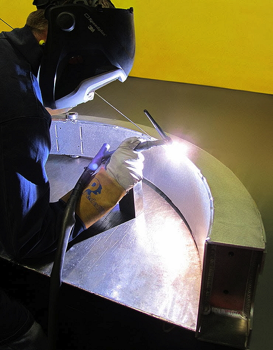
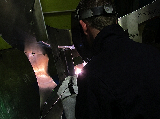
The structure shown in manufacture above is the intake hoop – so-called because its position, when joined to the hull, is adjacent to the engine air-intake. Fabricated in 6082-T6 aluminium alloy, the intake hoop contributes considerable additional strength and rigidity to the front of the boat. It was completed in April and will later be fitted with two diagonal bracing struts which will extend down diagonally from the top of the main hull to the tops of the sponsons.
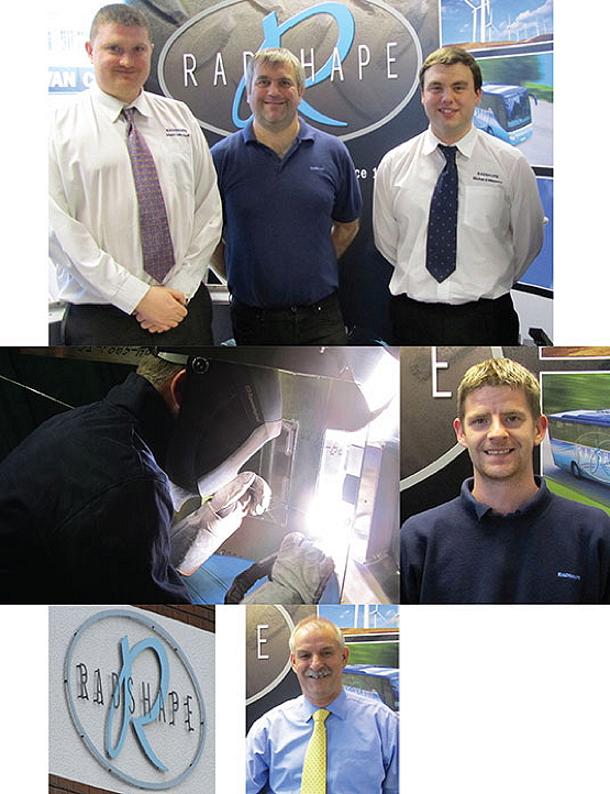
The intake hoop is one of several major components that have been manufactured to our design by Radshape Sheet Metal of Aston, Birmingham – who joined the Quicksilver project in 2007. We are extremely grateful for the considerable contribution Radshape’s highly-skilled specialists have made to our engineering effort to date. The welding has been done by Mark Patrick, who has 16 years’ experience in this trade with Radshape. Our thanks go to him, and to fabrication specialist Billy Howarth – who, having joined the firm 29 years ago, is Radshape’s longest-serving employee and has led the Aston company’s work on Quicksilver. Thanks also to Mark Mitchell and Richard Massey in the CAD department at Radshape, who take our 3D designs and turn them into workable CNC programmes so that all the constituent parts can be laser-cut from aluminium sheet. Mark has been with Radshape for 14 years, Richard ten.
Keith Chadwick, Radshape’s Managing Director, has conveyed to us his Board’s willingness for further structural parts for Quicksilver to be manufactured by the company in due course – a big boost to our plans.
Among the upper-hull components added earlier to the boat is the trunnion hoop – so called because it is situated astride the trunnion mounts (side mountings) of the engine. Primary function of the trunnion hoop – which is distinguished by its bright green colouring in the CAD images below – is to contribute strength and rigidity to the main hull module at one of its key structural junctures: the point where the rear sponson-arms, port and starboard, will exert significant loadings in the centre of the craft.
In a secondary function, the trunnion hoop is capable of supporting the weight of the engine. The Quicksilver team has not released any further details on this aspect of its design, beyond stating that the hoop is “adaptable in service”. Radshape delivered the trunnion hoop in January 2012.
A “sister” hoop structure situated close behind the trunnion hoop adds strength and rigidity to the rear part of the main hull module, and also serves as the upper-rear mounting point for the Spey engine. This hoop – which is coloured purple in the uppermost of the two images below – is referred to as the rear hoop and was fitted to the boat in 2008, having been manufactured to our design by Radshape in the early part of that year.
The rear hoop and trunnion hoop are both removable, so as to allow the engine to be installed or removed. They are both all-welded fabrications in high-performance aluminium alloy: 6082-T6 for the trunnion hoop and 7020-T6 for the rear hoop. The intake hoop is also removable – although it will seldom require removal, as it is located well clear of the engine.
Extensive employment of finite-element analysis (FEA) methods during the design phase of all three upper-hull hoop structures has ensured that they are as lightweight as they can possibly be, conducive with the required strength and stiffness requirements and appropriate safety margins. FEA helps us greatly in our understanding of the nature of the forces that are to be managed. And then from that point, “form follows function.”

Other notable features in the upper-hull region include the air-intake module. This is an all-composite, primarily carbonfibre, structure which internally directs air smoothly into the engine and externally serves as the outer skin of the craft in the area above and between the front and rear sponson-arms. The air-intake module will be held in place by several supporting structures (these are coloured red, pink and gold in the CAD images above).
An all-composite engine cover – comprising several sections, any or all of which are rapidly removable when access to the engine is required – will enclose the entire upper-hull area of the boat, providing a streamlined and waterproof outer skin. The engine cover will also contribute to the craft’s overall strength and rigidity, as it is being designed as a fully-stressed structural element.